How to make the right-angle Beacon
Low Profile USB Cable
With the introduction of the Low Profile assembly option, there are now two types of cable. They are NOT compatible, and using the wrong type may damage your Beacon. When you order a kit, the normal cable is included by default. This works for right angle and normal assembly. The low profile cable is different and available on request. If you have any concerns, ordered a kit, or would like to double check, see the USB Cables section.
Step 1 - Tools
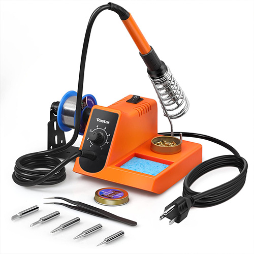
To create a right angle Beacon, you will need the following tools:
- Soldering Iron
- Solder
- Flux (optional)
- Wire cuter
Step 2 - Connectors
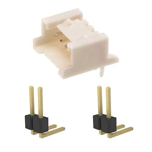
You also need the following pins and connector (which you should have received):
Step 3 - Print models
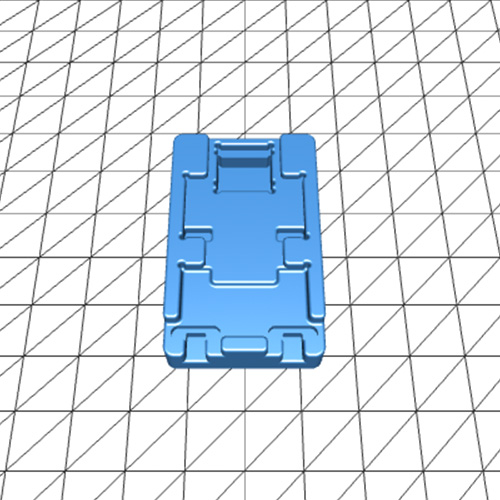
You will need to 3D print 2 CAD models which will provide the foundation to solder the Beacon correctly.
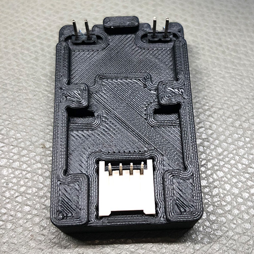
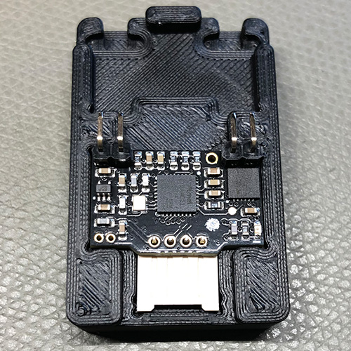
Step 4 - Placement
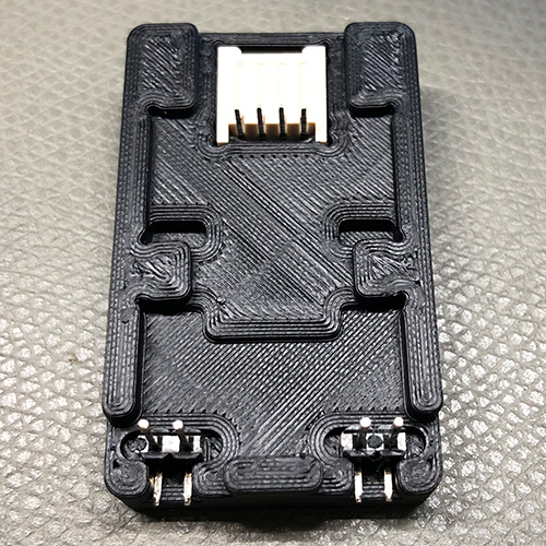
Place the connector and pin into your 3D foundation model as follows:
Step 5 - Inspect
Double check to make sure everything looks good:
Step 6 - Placement
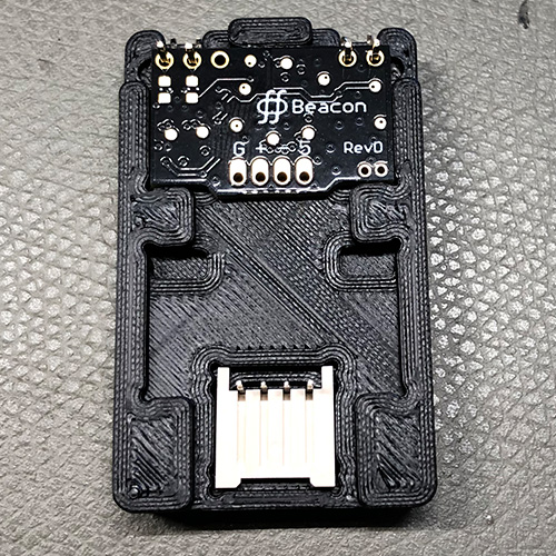
Place the amplifier PCB (the small rectangular one) in the foundation as follows:
Step 7 - Solder pins
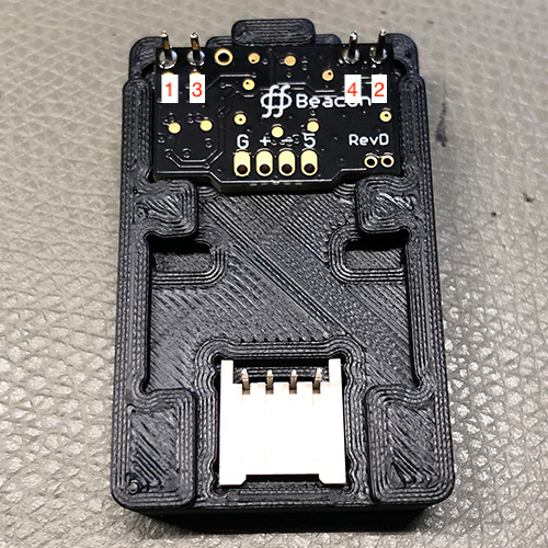
Solder the pins in the order shown:
Step 8 - Trim pins
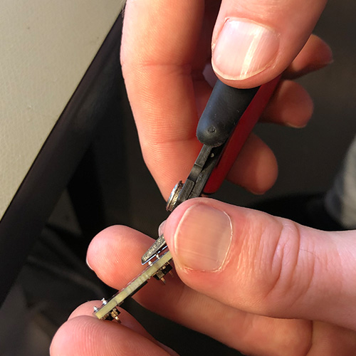
Remove the PCB and use a wire cuter to trim the pins you just soldered:
Step 9 - Placement
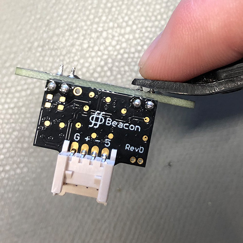
Place the amplifier PCB on the connector side in the orientation shown:
Step 10 - Solder pins
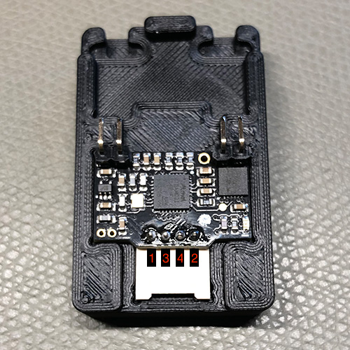
Solder the pins in the order shown:
Step 11 - Placement
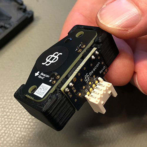
Get the second foundation ready and place the amplifier PCB and sensor PCB in the exact orientation shown:
Step 12 - Inspection
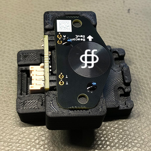
Place this second foundation with the PCBs on it on top of the first foundation as shown:
Step 13 - Solder pins
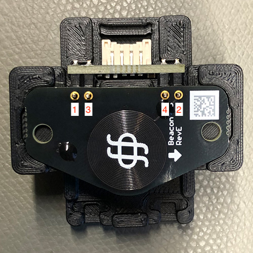
Solder the pins in the order shown:
Step 14 - Clip pins
Clip these newsly soldering pins with your wire cuter: