Beacon Contact
1. Introduction
Contact brings physical-touch nozzle probing to all Beacon devices. It works on the principle of z axis motion being interrupted by the nozzle coming into contact with the bed surface as seen in high resolution induction measurements. It is optimized to respond as quickly as possible to achieve low force on the printer mechanics and bed surface.
Contact may be used for the following:
-
Automatic Z-offset
-
Automatic Beacon model calibration for scan mode
-
Touch meshing for surfaces unsuitable for scan mode
It enables automated workflows for dealing with nozzle swaps and bed plate changes.
Ramming Speed
Beacon Contact works by physically bringing the nozzle into contact with the bed. A misconfiguration could ruin your day, so fully read the major sections of this documentation to understand the tools that are provided to you for a safe experience, and proceed slowly at first.
Innovation and Risk Taking
Beacon3D is committed to bringing the best new technology to our customers. We revel in attacking the highest impact solutions regardless of the engineering challenges. Induction contact sensing was chosen as the most reliable solution over alternative methods. While we are committed to the highest standards of hardware and software quality, no test regimen is perfect and there are endless avenues for abuse or misuse. Ultimately, use of this solution is at your own risk.
2. TrueZero
Contact is the first direct nozzle probing technology achieving low force, temperature insensitive thresholding with no moving parts and zero offset. Bed surfaces capable of probing at print temperatures can achieve a zero baby stepping, true zero offset calibration automatically.
Examples of hard, robust surfaces able to achieve TrueZero are raw steel, powder coated pei, or thin glass over aluminum.
Nozzle Ooze
Adopting nozzle homing workflows adds new sources of possible error. Additional mitigations may be required to keep the nozzle clean during contact probing.
Smooth PEI
Despite the low contact force, some surfaces such as thin PEI laminations are susceptible to melting when exposed to a print temp nozzle. For such materials, probing at reduced temperatures is strongly recommended.
2.1 Broader Surface Support
If you work with less robust bed plates or often print filaments known to ooze significantly, you would be better served by probing at reduced nozzle temperatures.
Hotend Thermal Expansion
Probing at reduced nozzle temps will require the use of additional, generally positive, offsets to account for hotend thermal expansion when heating the nozzle to the final print temp.
3. Basic Requirements
- Beacon must be approaching a metallic target when the nozzle comes into contact with the bed.
- Beacon must be rigidly coupled to the hot end, such that its motion is interrupted by nozzle contact.
Under nearly all typical Beacon printer setups, these two requirements are satisfied by having a metallic bed or subsurface, and having Beacon mounted in close proximity to the hotend.
Non Rigid Toolheads
Flexures or other moving parts decoupling the hotend from Beacon must be immobilized or redesigned to work properly with contact.
4. Contact Workflows
Contact and induction (proximity) homing can be used together to optimize your workflow. For an operator who uses only 1-2 bed plates and doesn't often swap nozzles, induction remains a reliable solution without worry about nozzle ooze management. An operator that mixes and matches many plates, toolheads, print temperatures, or nozzles would be best served by a contact oriented workflow that calibrates itself on every print.
4.1 Contact Z-Offset and Auto-Calibration
Contact can be used to generate a new beacon model calibration and z offset calibration on every print. This enables workflows that never store a beacon model, and deal with nozzle or bed plate changes automatically.
The G28 homing command can be configured to home the machine using contact and generate a new model each time.
Suggested configuration options for this workflow:
4.2 Contact Auto-Calibration with Induction Homing
Contact can be used to enhance the traditional Beacon workflow with the addition of the BEACON_AUTO_CALIBRATE command. This will use contact system to automatically calibrate a Beacon model without using manual paper processes, making it quicker and easier to update your models after the occasional nozzle or plate change.
Safe Home Position
Like BEACON_CALIBRATE, the BEACON_AUTO_CALIBRATE command allows a Beacon model to be calibrated at any X/Y position, requiring the toolhead to be manually positioned at the desired location before beginning.
The G28 homing command can be configured to use induction proximity via a Beacon model loaded from the configuration file and calibrated previously. This was the traditional operating mode of Beacon.
Suggested configuration options for this workflow:
For convenience, G28 behavior can be adjusted on the fly via parameters. For example, G28 Z METHOD=CONTACT CALIBRATE=1 will do the equivalent of BEACON_AUTO_CALIBRATE, but additionally move the toolhead to the homing position first.
5. Quick Setup
5.1 Firmware Update
Contact includes the first firmware update for Beacon.
Update your beacon_klipper installation using the UI or by running git pull from the command line. You will need to use ssh and manually run ./update_firmware.py update all or ./install.sh from the beacon_klipper directory to load the new Beacon device firmware.
Make sure that you restart the klipper service via the UI or with the command sudo service klipper restart after updating.
5.2 Configuration
Beacon now provides safe_z_home equivalent functionality for easy, probe offset aware switching between induction and contact homing modes. The existing safe_z_home section should be removed before adding the new settings. These are recommended defaults for a full contact workflow and should be added to the [beacon] section:
[beacon]
contact_max_hotend_temperature: 180 # increase to probe at print temps

home_xy_position: 117.5, 117.5 # update with your safe position
home_z_hop: 5
home_z_hop_speed: 30
home_xy_move_speed: 300
home_method: contact # use proximity for induction homing
home_method_when_homed: proximity # after initial calibration use induction
home_autocalibrate: unhomed # contact will calibrate beacon on first home
With these settings, the first home at power on will use contact to calibrate beacon for scan mode. Subsequent homes will use the newly generated calibration model.
Homing Override
This new safe_z_home functionality does not work with homing_override. If overrides are only required in your setup for sensorless homing, we would suggest looking at Kalico for its more native sensorless implementation. Otherwise consult Section 8.2 for more information.
5.3 Print Start GCODE
The following is a summarized recommendation for the sequence of events when a print starts, which will need to be mixed in with your existing start routine.
For maximum surface flexibility, the following setup probes at reduced nozzle temperature to avoid damaging smooth pei, and to manage oozing of runnier filaments. With this setup, hotend thermal expansion from heating to printing temperature will require an additional offset to avoid too much squish.
BED_MESH_CLEAR
SET_GCODE_OFFSET Z=0

G28     ; home axes
G0 Z2   ; position beacon at 2mm for heat soak

M140 S{BED}     ; start bed heater
M109 S150       ; preheat nozzle to probing temp
M190 S{BED}     ; wait on bed temperature
G4 P60000       ; optional, let temps settle for 1 min

WIPE_NOZZLE     ; call another macro to wipe nozzle if available

G28 Z METHOD=CONTACT CALIBRATE=1    ; calibrate z offset and beacon model hot
Z_TILT_ADJUST                       ; or QGL to balance towers
BED_MESH_CALIBRATE RUNS=2           ; bed mesh in scan mode

WIPE_NOZZLE
G28 Z METHOD=CONTACT CALIBRATE=0    ; calibrate z offset only after tilt/mesh

M104 S{EXTRUDER}                    ; set extruder to print temp
M109 S{EXTRUDER}                    ; wait for extruder temp

SET_GCODE_OFFSET Z=0.06     ; add a little offset for hotend thermal expansion
                            ; needs fine tuning, long meltzones require more
SET_GCODE_OFFSET Z_ADJUST={OFFSET}  ; apply optional material squish via slicer

PRIME_NOZZLE    ; call another macro to purge or prime nozzle
; start printing
Hotend Thermal Expansion
For maximum compatibilty the above example probes at reduced temp, requiring an additional offset to compensate for the hotend heating to print temp. In the future, automated tools will be provided to measure and compensate this effect.
High flow and ultra high flow hot ends have a long melt zone and will require a larger offset than the 0.06mm suggested above.
Zero Reference Position
We always recommend configuring zero_reference_position for your bed mesh, which improves flexibility to allow z rehoming after mesh measurement. Some of the configurations shown require it to work correctly. It should normally match the position used for home_xy_position.
5.4 First Contact Checklist
Here is a brief list of items to check before your first contact homing attempts:
-
Beacon mount meets the Z-offset specification, which means it should be mounted only around 3mm higher than the nozzle tip.
-
Metal is present in the bed stack, with materials on top of the metal not thicker than 3-4mm.
Weak Signal
If these requirements are not followed, the signal may be too weak to properly trigger. Exercise additional caution if you choose to proceed anyway, and be ready to hit the emergency stop if necessary.
With the contact configurations from above, G28 will now home the X, Y, and then Z axis.
For safety and peace of mind, the LED will turn on as soon as the contact system determines it has a strong enough signal for detection. It should normally turn on up to 10mm in advance of the metal target, allowing enough time to manually estop the machine if necessary.
High Noise Z
Contact is optimized to support a wide range of operating conditions, however Z axes with extraordinary noise may have trouble establishing a base line signal. First contacts on a new machine should always be done cautiously with an eye on the LED to ensure it is arming correctly, and a finger on the estop button to abort if necessary.
Safe Testing
If you have any doubts about your setup, we suggest consulting the section 6.6 Safely Testing Surfaces first.
6. Detailed Requirements
When experimenting with different surfaces and setups, it is highly recommended to start off with the BEACON_POKE command which has extra safety features.
6.1 Metallic Target
The metallic target required for contact is more flexible than for scan mode. Contact is immune to fixed permanent magnets and metallurgical material variations. Further it is largely insensitive to the exact distance of the target, minor tilting of the toolhead, or discontinuities in the surface such as small holes or grooves.
As with scan mode, the quality and distance of the target does affect the quality of the reading, so in extreme cases the provided tools should be used to assess the achieved precision.
The low required contact force has been shown to work well with stiff spring mounted beds, as well as beds with a small amount of flex that can be problematic for alternative solutions.
Probe Offset
Though contact is made at the nozzle, induction measurements are made at the probe. The user must take care not to configure or initiate contact operations with the probe off the side of the bed.
6.2 Beacon Mount
Contact requires that Beacon's motion is stopped simultaneously with the nozzle when contact is made. Flexures and other moving parts decoupling the hotend from Beacon must be immobilized or designed out.
For a typical toolhead design with beacon mounted up next to the hotend this requirement is normally met. Under extreme mounting conditions where beacon may be mounted far away from the nozzle or on the opposite end of a significant lever the behavior should be assessed with the provided tools.
6.3 Z Axis Noise
In extreme cases Z axis noise may limit the precision and/or ability to arm the contact system correctly. The Armed output of the BEACON_POKE provides a means of determining how far in advance of the surface a minimally viable signal is established. It must be used with a considerable additional safety margin to ensure reliable operation.
6.4 Bed Surfaces
6.4.1 Contact + Proximity
For hybrid workflows using contact and proximity modes, the requirements for scan mode should be followed. This prefers native metal flex plates or thin stack ups over metal. The thicker the layers on top, the more likely they may mismatch with the metal being scanned underneath.
6.4.2 Contact Only
Contact only workflows open new options for thicker surface materials, embedded magnet beds, or surfaces suffering metallurgical consistency issues. When Beacon is mounted optimally, contact will typically support stackups up to 3-4mm thick over metal. Materials pushing the limits should be assessed with the provided tools.
6.4.3 TrueZero Compatibility
Hard surfaces capable of high temperature probing will be able to find the exact, true zero.
Despite the low contact force, soft materials may compress slightly while probing, resulting in more squished first layers. These materials may require additional applied offsets.
Filaments known to ooze are best managed by probing at reduced temperatures, and will require additional offset for the first layer due to hotend thermal expansion.
| Surface | Hard Surface | High Temp Probing | TrueZero | Scan Mode |
|---|---|---|---|---|
| Raw Steel + Glue | Yes | Yes | Yes | Yes |
| PEI Textured | Yes | Yes | Yes | Yes |
| Smooth PEI | No | No | No | Yes |
| Thin Glass over Aluminum | Yes | Yes | Yes | No |
| Thin G10 / FR-4 | Yes | No | No | Yes |
Mechanical Irregularities
Some machines may have minor mechanical irregularities such as backlash or toolhead play which could require small additional offsets.
First Layer Squish
Desired first layer squish is a highly personal preference, so you may want to apply additional offsets to meet your taste.
6.5 Nozzle Hygiene
Nozzle ooze can interfere with accurate nozzle probing. For filaments known to be high ooze, probing at reduced nozzle temperatures (150C) is strongly recommended.
When viable, nozzle wipers can improve probe consistency print to print. Our suggestion would be to pursue solutions using silicone materials, and wipe immediately before contact operations. Brass bristle brushes run the risk of shorting circuits on Beacon if not mounted and managed carefully.
For some lower ooze filaments, a good retraction on print end and reduced temperature probing can be sufficient. If necessary, the acceptance tolerance for contact can be relaxed slightly with the autocal_tolerance configuration option for a small loss of precision. Manual cleaning in between prints may be sufficient in some instances.
6.6 Safely Testing Surfaces
The new command BEACON_POKE allows contact to be tested with safeguards for maximum overshoot by specifying top and bottom z coordinates. The contact system will be activated and the toolhead will approach until the specified bottom value.
For safety and peace of mind, the LED will turn on as soon as the contact system determines it has a strong enough signal for detection. It should normally turn on up to 10mm in advance of the metal target, allowing enough time to estop the machine if necessary.
The Armed output provides a quantitative means of determining how far in advance of the surface a minimally viable signal is established.
Once a valid coordinate system is established, the typical usage is:
BEACON_POKE TOP=4 BOTTOM=-0.3
If poke produces consistent results for a given surface, it is safe to run auto calibration procedures.
Contact Lead-in Distance
Contact requires a small, less than 1mm typically, lead-in during its initial approach to trigger correctly. This is provided automatically by the calibration routines, however BEACON_POKE gives direct control over the top height so the operator must factor this in.
7. Contact Performance
There are many factors that affect performance of the contact system. The primary indicators are the self reported latency parameter, the variation of the reported z values, and the armed distance.
7.1 Detection Latency
Latency is an overall rating of systemic noise present when nozzle contact is made. A lower latency value means that less total noise is present, and that the system can react more quickly upon contact.
Higher latency means there will be a slower reaction, more z distance overshoot, and more total force developed upon contact.
Total Force Development
Contact latency is the first part of force development, with single board computer performance and Z axis MCU latency also playing a role. Native USB is recommended for the z axis MCU to achieve the lowest force numbers.
Axis motion noise, sensor noise, optimal sensor mounting and thickness of non metallic target material in the stackup all contribute to increased latency. The following table lists how we would rate latency results.
| Score | Notes |
|---|---|
| 0-1 | Extremely low noise, rarely achieved |
| 2-4 | Excellent performance for a typical printer |
| 5-8 | Acceptable performance, machine may have considerable cyclic axis noise |
| 9-11 | Not ideal, may want to verify proper mounting or use thinner stackups |
| 12-14 | Reason for concern, present setup may be risky to continue with |
The primary means of reviewing contact latency is with the output from the BEACON_POKE command.
7.2 Z Result Precision
For some set ups, it is possible to achieve high precision even when the latency is poor. These results are tied more to the magnitude of the contact signal than the background noise.
Examples of things that can affect the Z result precision are:
-
Z axis noise
-
Toolhead rigidity
-
Target surface hardness
-
Nozzle tip surface area
-
Nozzle ooze
Setups which strongly interrupt toolhead motion upon contact will result in more precise Z results.
Achievable Precision
Printer designs with typical noise and strong contact impulses are capable of sub-micron standard deviations.
The primary means of reviewing Z precision is the standard deviation readout of auto calibration operations or by reviewing repeated Z measurements from the BEACON_POKE command.
7.3 Armed Distance
This metric reports the distance from the surface that a minimal signal was established to activate the contact system. It puts a hard upper bound on how thick of a material can possibly be probed in a particular setup. Considerable additional safety margin will be required for safe probing and to achieve a usable precision.
Minimal Signal
Armed distance indicates where contact is first activated relative to the surface. Attempting to probe something thicker will result in a crash 100% of the time.
Armed performance is closely related to the latency, and affected by the same machine design elements. Axis noise, metallic target quality, and target distance to Beacon are the primary constraints.
Beacon Poke
To measure Armed distance correctly you will likely need to increase the top parameter on BEACON_POKE to 10mm or more.
7.4 False Triggers
False triggers may occasionally occur in the presence of extraordinary noise beyond the background level. This could be caused by a hard bump to the machine, a sticky spot in the motion system, or a brief stutter in the z axis movement.
Most contact operations have integrated retry logic and will naturally reject and recover from a one off false trigger. If a machine experiences repeated false triggers, especially around a single z position, mechanical sources of rough spots should be investigated.
7.5 Force Estimate
Probe force for a given machine is determined by the amount of z overshoot and the mass / rigidity of the toolhead. Overshoot is dependent on the contact latency, and how fast the machine can stop the z axis.
The BEACON_POKE command outputs the contact z position and the total overshoot. This can be use for estimating the static force on the toolhead.
Below is a table of measurements from various size machines to estimate force for a given setup:
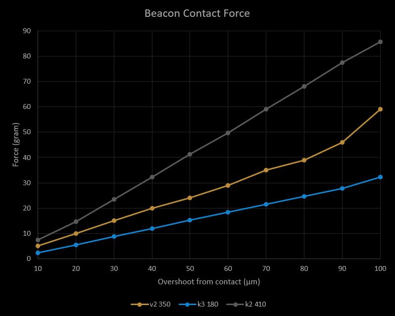
Achievable Force
Printers with typical z axes generally achieve less than 30um overshoot, and forces as low as 10 to 20 grams.
7.6 Probing Speed
Thorough testing has shown that 3mm/s is optimal for most configurations. If you desire to play with this parameter, we would suggest sticking to the 2-4mm/s range with 5mm/s as the upper end. Higher speeds may put excessive strain on the mechanics, especially when considering worst case scenarios, and they have not been tested as thorougly for correct function.
Always use BEACON_POKE first for safety, and watch out for excessive overshoot, early triggers and/or probed value drift due to the added strain.
When adjusting speed, if the latency does not improve, then the resulting precision will generally be worse.
7.7 Noise Tolerance
Configuration options contact_sensitivity and contact_latency_min were added to adjust noise tolerance in firmware 2.1.0 for unusually noisy machines. Most machines will never need to change these.
sensitivity adjusts the required noise levels for automatically advancing contact latency, making it a dynamic option for machines with general high noise levels that often experience random early triggers. Configuration values range from 0 to 3 where 0 is standard and each additional point increases the noise tolerance.
latency_min puts a lower limit on the latency permitted by the contact processor, blocking it from advancing to levels more susceptible to noise. It is primarily useful for machines with specific rough spots that show up as early triggers, or on machines where the noise results in erratic latencies affecting contact repeatability.
For users experiencing many early triggers or highly inconsistent latency, our first suggestion would be to set contact_sensitivity: 1 to see if dynamic management is sufficient. If not, we would next try setting contact_latency_min to a value slightly higher than typical results reported by BEACON_POKE. In most cases, machines requiring latency_min should also use sensitivity.
Both settings will increase the typical latency of contact, resulting in slower response and higher activation forces. In our experience, lower latencies typically achieve more precise contact results, therefore these options should only be used when noise issues are present.
Noise and Reliability
It is always advisable to attempt to improve noise by mechanical or electrical tune up first. This could include things such as cleaning and greasing motion components, tightening bolts, adjusting z microstepping, adjusting z motor current, etc. Requiring these noise mitigation settings is an early warning that the machine z axis is rough and could result in imprecise results or worse. If sensitivity >= 2 or latency_min >= 8 is required, the user should proceed cautiously or consider sticking to induction homing methods.
8. Extended Configuration
8.1 TrueZero
If you run primarily low ooze filaments with high temp tolerant surfaces, you can probe at print temp and run with zero offset.
The recommended start process would be to calibrate beacon with a hot bed and mid range nozzle temp (150C) for bed meshing, and then do a final z offset with print temperature nozzle before starting the print.
This requires zero_reference_position for the bed mesh to be configured, so that z can be rehomed after the mesh was measured. contact_max_hotend_temperature must be set in the [beacon] config section to enable probing at temps that may damage some surfaces.
A reduced example would be like this:
M109 S150       ; preheat nozzle to probing temp
WIPE_NOZZLE     ; call another macro to wipe nozzle if available

G28 Z METHOD=CONTACT CALIBRATE=1    ; calibrate z offset and beacon model
Z_TILT_ADJUST                       ; or QGL to balance towers
BED_MESH_CALIBRATE RUNS=2           ; bed mesh in scan mode

M104 S{EXTRUDER}                    ; set extruder to print temp
M109 S{EXTRUDER}                    ; wait for extruder temp
G4 P20000                           ; give the hot block 20s to stabilize

WIPE_NOZZLE
G28 Z METHOD=CONTACT CALIBRATE=0    ; calibrate z offset only with hot nozzle

SET_GCODE_OFFSET Z_ADJUST={OFFSET}  ; apply optional material squish via slicer

PRIME_NOZZLE    ; call another macro to purge or prime nozzle
8.2 Homing Override
The Beacon safe_z_home functionality does not work with homing_override, below is an example for how to get similar functionality using homing hooks provided by the Beacon safe_z_home instead.
The homing hooks replace homing_override, and belong in [beacon]:
home_gcode_pre_x: _HOME_PRE_AXIS AXIS=X
home_gcode_post_x: _HOME_POST_AXIS AXIS=X
home_gcode_pre_y: _HOME_PRE_AXIS AXIS=Y
home_gcode_post_y: _HOME_POST_AXIS AXIS=Y
This still uses the Beacon safe_z_home, so the following are needed in [beacon] for a typical setup:
home_xy_position: 150, 150 # update with your bed center
home_z_hop: 3
home_z_hop_speed: 30
home_xy_move_speed: 150
home_method: contact # use proximity for induction homing
home_method_when_homed: proximity # after initial calibration use induction
home_autocalibrate: unhomed # contact will calibrate beacon on first home
New macros are required, here are staring examples:
[gcode_macro _HOME_PRE_AXIS]
gcode:
  # Adapt this for your printer.
  {% set HOME_CURRENT = 0.5 %}
  SET_TMC_CURRENT STEPPER=stepper_x CURRENT={HOME_CURRENT}
  SET_TMC_CURRENT STEPPER=stepper_y CURRENT={HOME_CURRENT}

[gcode_macro _HOME_POST_AXIS]
gcode:
  {% set axis = params.AXIS %}
  {% set RUN_CURRENT_X = printer.configfile.settings['tmc2209 stepper_x'].run_current|float %}
  {% set RUN_CURRENT_Y = printer.configfile.settings['tmc2209 stepper_y'].run_current|float %}

  # Move away
  SAVE_GCODE_STATE NAME=home_post_axis
  G91
  G0 {axis}-10 F3600
  RESTORE_GCODE_STATE NAME=home_post_axis

  # Make sure StallGuard registers are cleared
  M400
  # Set current during print
  SET_TMC_CURRENT STEPPER=stepper_x CURRENT={RUN_CURRENT_X}
  SET_TMC_CURRENT STEPPER=stepper_y CURRENT={RUN_CURRENT_Y}
Be prepared to E-Stop your machine if necessary during initial testing.
9. New Commands and Parameters
9.1 G28
If using the Beacon safe_z_home functionality, new options are added to G28 to switch between homing methods on the fly.
G28 Z METHOD=CONTACT CALIBRATE=1 will use contact to find zero offset, and then calibrate a beacon model for scan mode. Setting CALIBRATE=0 can skip beacon model creation to save time.
G28 Z METHOD=PROXIMITY will do a quicker homing with induction if a Beacon model is available. Take care that the model corresponds to the plate presently in your machine.
9.2 BEACON_AUTO_CALIBRATE
BEACON_AUTO_CALIBRATE is an automated version of BEACON_CALIBRATE that uses the contact system to find the zero offset instead of using paper. This makes it easy to recalibrate on the fly.
This is useful for replacing manual paper calibration in induction homing workflows, or to perform automatic calibrations without depending on the new G28 enhancements.
Homing XY Position
Unlike the new G28 enhancements, BEACON_AUTO_CALIBRATE will not move the machine in X or Y before initiating contact. The toolhead must be positioned manually before calling this command.
9.3 BEACON_POKE
BEACON_POKE perfoms a contact probe at the present location with configurable guardbands. BOTTOM and TOP parameters bound the beginning and end z coordinates to limit overshoot.
This is useful for safely testing the contact system on new materials, with new ooze management systems, etc.
9.4 BEACON_OFFSET_COMPARE
BEACON_OFFSET_COMPARE compares probe readings between contact and proximity modes for debug purposes. It will initiate contact probing at the present position, and then move over by the probe offset for proximity measurement.
This is useful for debugging toolhead twist, magnetic, or metallurgical issues.
9.5 BED_MESH_CALIBRATE
BED_MESH_CALIBRATE can be switched between between contact and induction by setting PROBE_METHOD=CONTACT or PROBE_METHOD=PROXIMITY.
To facilitate 1:1 comparisons of contact and scan mode meshes for debug purposes, the option USE_CONTACT_AREA will shrink the scan mode mesh area to match the contact mesh area.
The default behavior for contact meshes is to reduce the configured mesh size to account for probe offsets. The reduced area can be reclaimed by configuring a contact specific mesh area with the options contact_mesh_min and contact_mesh_max of the [beacon] section.
9.6 Z_TILT_ADJUST QUAD_GANTRY_LEVEL SCREWS_TILT_ADJUST DELTA_CALIBRATE PROBE
The above commands can also be switched between probe modes using the PROBE_METHOD option and parameters CONTACT or PROXIMITY.
10. Config Reference
[beacon]
#default_probe_method: proximity|contact
# Sets the default probing method for mesh, tilt, qgl, probe, etc.
#contact_max_hotend_temperature: 180 # increase to enable hot contacting
# Temperature limit for the hotend when contacting, override this for temps which may damage some surfaces.
#contact_sensitivity: 0
# Adjusts noise tolerance of contact processing. Values 0-3 are valid, with 3 tolerating the most noise.
#contact_latency_min: 0
# Limits how low of a latency contact is allowed to advance.

# new additions for beacon safe_z_home functionality
home_xy_position: 117.5, 117.5
# X, Y coordinate for homing z via contact.
#home_z_hop: 5
# Distance to retract before x/y homing moves.
#home_z_hop_speed: 30
# Retraction speed for z hop.
#home_xy_move_speed: 300
# Speed for moving to home_xy_position.
#home_y_before_x: False
# If set, the Y axis will home first when using the beacon safe_z_home

# new additions for setting default homing mode
home_method: contact|proximity
# Sets default homing method used by G28. `proximity` requires a valid beacon model to be loaded.
#home_method_when_homed: contact|proximity # defaults to `home_method` value
# Sets the homing method when the machine is already in a homed state.
#home_autocalibrate: always|unhomed|never
# Sets the autocalibration behavior. `always` will autocal on every home, `unhomed` on initial homing,
# `never` will never so that models stored in config may be used with proximity homing.

#home_gcode_pre_x: _HOME_PRE_AXIS AXIS=X
# Enables a gcode macro before homing the x axis
#home_gcode_post_x: _HOME_POST_AXIS AXIS=X
# Enables a gcode macro after homing the x axis
#home_gcode_pre_y: _HOME_PRE_AXIS AXIS=Y
# Enables a gcode macro before homing the y axis
#home_gcode_post_y: _HOME_POST_AXIS AXIS=Y
# Enables a gcode macro after homing the x axis

#contact_activate_gcode: _CONTACT_ACTIVATE
# Enables a gcode macro to be called before contact is activated
#contact_deactivate_gcode: _CONTACT_DEACTIVATE
# Enables a gcode macro to be called after contact is deactivated

# new autocalibration config options
#autocal_speed: 3
# Speed during contact movement. Probing outside of 2-5mm/s not recommended and at your own risk.
#autocal_accel: 100
# Acceleration of autocal movement.
#autocal_retract_dist: 2
# Retract distance between autocal samples.
#autocal_retract_speed: 10
# Speed of autocal retraction move.
#autocal_sample_count: 3
# Number of samples used for each autocal.
#autocal_tolerance: 0.008
# Acceptance tolerance for an autocal result.
#autocal_max_retries: 3
# Number of retry attempts permitted when tolerance is exceeded.
11. Command Reference
11.1 BEACON_POKE
BEACON_POKE [SPEED=<speed>] [BOTTOM=<z_bottom>] [TOP=<z_top>]:
Performs a contact operation with added safeguards for assessing performance and running experiments.
11.2 BEACON_AUTO_CALIBRATE
BEACON_AUTO_CALIBRATE [SPEED=<speed>] [ACCEL=<accel>] [RETRACT=<retract_dist>] [RETRACT_SPEED=<retract_speed>] [SAMPLES=<sample_count>] [SAMPLES_TOLERANCE=<samples_tolerance>] [SAMPLES_TOLERANCE_RETRIES=<samples_tolerance_retries>] [SKIP_MODEL_CREATION=<1>]:
Uses Contact to find zero and perform a BEACON_CALIBRATE routine automatically. Calibration will be performed at the machine's present X, Y coordinate. SKIP_MODEL_CREATION can be used to skip the scan mode model calibration step, and do only the z offset.
11.3 BEACON_OFFSET_COMPARE
BEACON_OFFSET_COMPARE [TOP=<z_top>]:
Performs a comparison of contact and proximity measurements at the present position for investigating mismatches between the two modes.
12. Command Enhancements
12.1 G28
G28 [<axes>] [METHOD=<contact|proximity>] [CALIBRATE=<0|1>]:
If using the safe_z_home functionality, new options are added to G28 to choose homing method -- contact or proximity -- and when to recalibrate the beacon model used for proximity.
12.2 BED_MESH_CALIBRATE
BED_MESH_CALIBRATE [PROBE_METHOD=<contact|proximity>] [USE_CONTACT_AREA=<0|1>]:
PROBE_METHOD provides a means for switching between contact and proximity (scan) meshes. USE_CONTACT_AREA can be used to shrink the size of the scan mode mesh to match the points probed by contact for 1:1 comparisons.
12.3 Z_TILT_ADJUST QUAD_GANTRY_LEVEL SCREWS_TILT_ADJUST DELTA_CALIBRATE PROBE
<COMMAND> [PROBE_METHOD=<contact|proximity>]:
PROBE_METHOD is added to the above commands for switching between contact and proximity modes.